Hi,
at the VCFB I got my Gigatron kit.

- Kit003.jpg (371.59 KiB) Viewed 4127 times
Yesterday I soldered it. I started with the resistors.

- PCB001.jpg (342.42 KiB) Viewed 4127 times
Then the IC sockets were soldered - I want to have the possibility to swap nonworking ICs and I want to have the possibility to change the hardware by removing one ore more ICs and possibly insert an additional board in future.
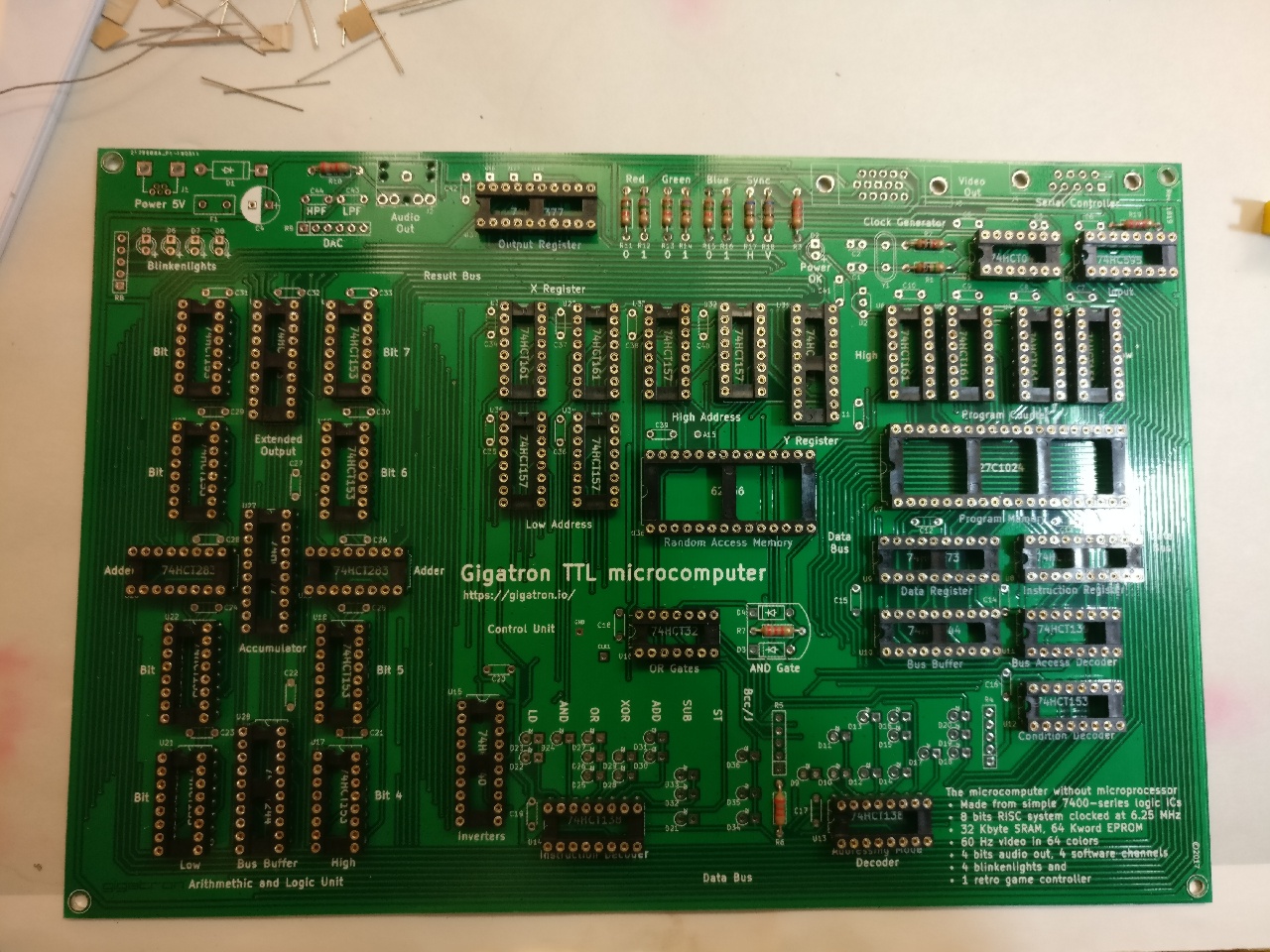
- PCB002.jpg (502.11 KiB) Viewed 4127 times
The board is finished.
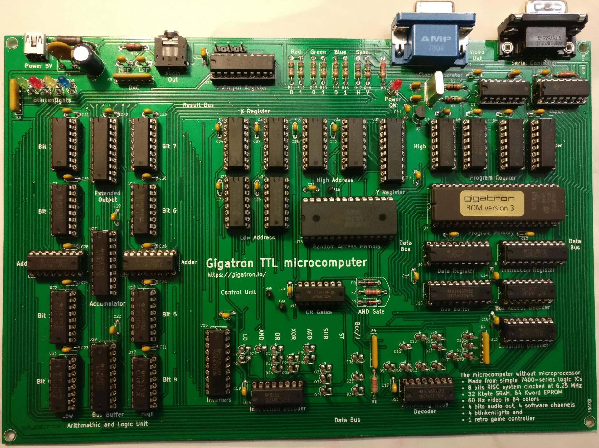
- PCB003_.jpg (476.11 KiB) Viewed 4127 times
The backsize after cleaning.

- PCB004.jpg (423.41 KiB) Viewed 4127 times
The case was prepared to mount the board.

- case001.jpg (256.98 KiB) Viewed 4127 times
It's mounted.
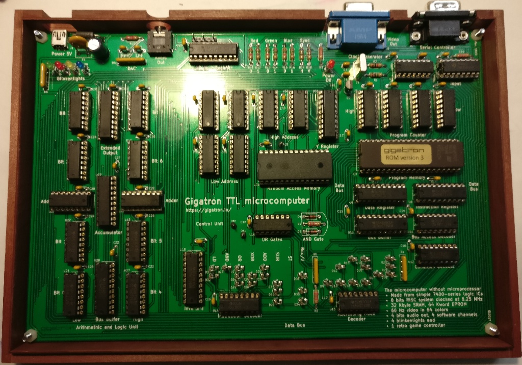
- InCase001.jpg (334.26 KiB) Viewed 4127 times
The board was mounted to vertically center the jacks in the case.

- Back001.jpg (83.49 KiB) Viewed 4127 times
I checked the audio circuit and found it to be not ok to have a load of 2 kOhm after the D/A controller 2R2 network which has a source resistance of 10 kOhm. Therefore I removed C43, C44 and R10. Instead of C44 I soldered a series circuit of 47 kOhm and 22 nF. R 10 was substituted by a parallel circuit of 42 kOhm and 1.2 nF.

- Audio_001.jpg (55.53 KiB) Viewed 4125 times
After that the R2R network is loaded with about 100 kOhm (42 k + 47 k), the source resistance of the audio jack is 24 kOhm and the output voltage is 2 V peak to peak or 0.7 Veff. The low pass frequency is about 5.5 kHz and the high pass frequency is about 127 Hz. The sound is powerfull and ok for me. The input resistance of the amplifier connected to the audio output of the Gigatron should be as high as possible (more than 100 kOhm would be good - I will build an amplifier into a speaker box, I own).

- Final001_.jpg (470.06 KiB) Viewed 4127 times
Next steps is to check all the possibilities that are give by a computer based on TTL chips without single chip CPU.
Greetings Ingo.